
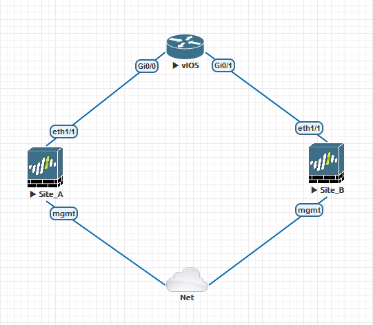
This posts covers implementing a ‘tunnel VRF’ topology detailed in <this post>. Essentially we are providing a method of routing between customer VRs across a WAN via (IPSec) tunnel, without needing to import the WAN routing table prefixes into customer VR. Arguably you could have the customer and WAN prefixes in one routing table and control flows towards the WAN via Security Policy, but what happens if you then need to provision another customer VR which needed access to the WAN for tunneling? You could leak the necessary routes between the VRs, but then one customers traffic is being transported on the routing table of another customer. There may be security implications in this! Using this topology, you will start with a WAN and then have any number of addtional customer VRs.
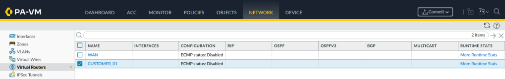
We start with configuring two Virtual Routers ‘WAN’ and ‘CUSTOMER_01’:
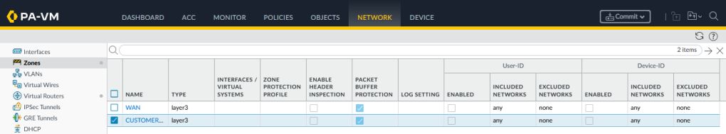
At this stage we only need two Security Zones ‘WAN’ and ‘CUSTOMER_01’, they both need to be of type ‘Layer3’, we will assign the interfaces shortly:
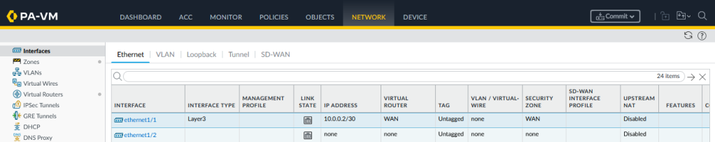
We are only connecting to one upstream router on the WAN, so lets configure Ethernet1/1 with a unqiue /30 subnet, assigning it to the ‘WAN’ VR and Security Zone:
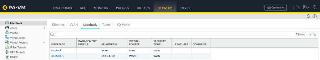
We could configre the Ethernet1/1 interfaces as the IKE gateway, but in the future you may need to be dual-homed, in which case you need an IP which can reachable despite link status of the WAN interfaces. To acheive this we need to configure a loopback interface. Just make sure that the upstream router has a route to reach this loopback IP via the firewall WAN interface(s).
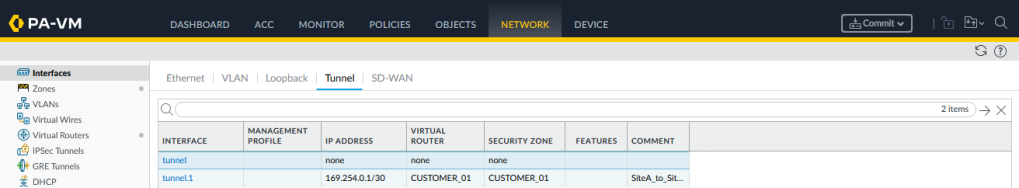
Now setup a tunnel interface which will be strung between the two firewalls:
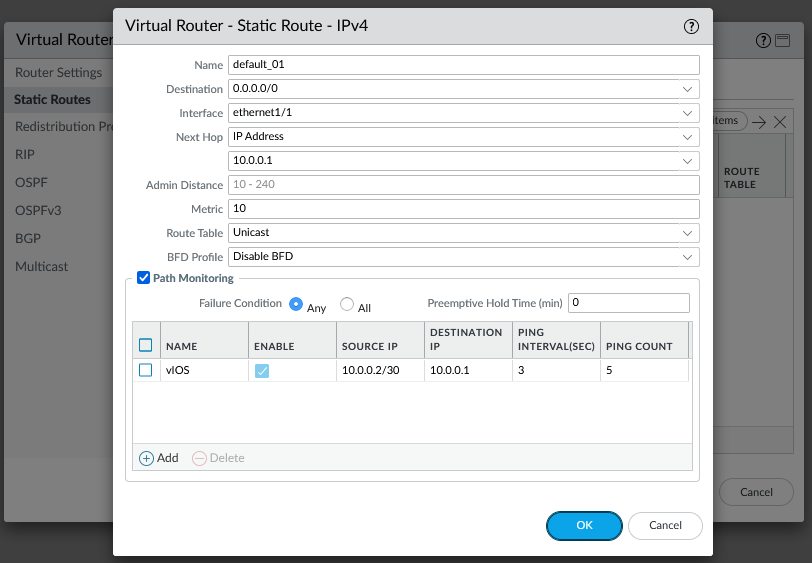
To keep things simple we are not running BGP with the upstream routing, so a static route to reach the other firewall loopback interface IP (2.2.2.2/32) or just setup a default route. Also configure static route monitoring out of good habit:
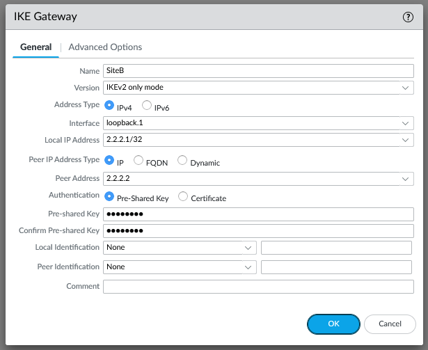
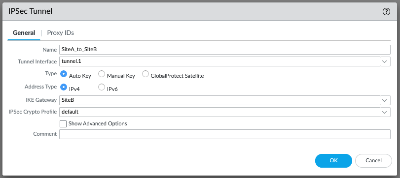
Now onto the IPSec tunnel, our local IKE gateway is the WAN loopback interface and the peer address is the opposing loopback on the SiteB firewall:
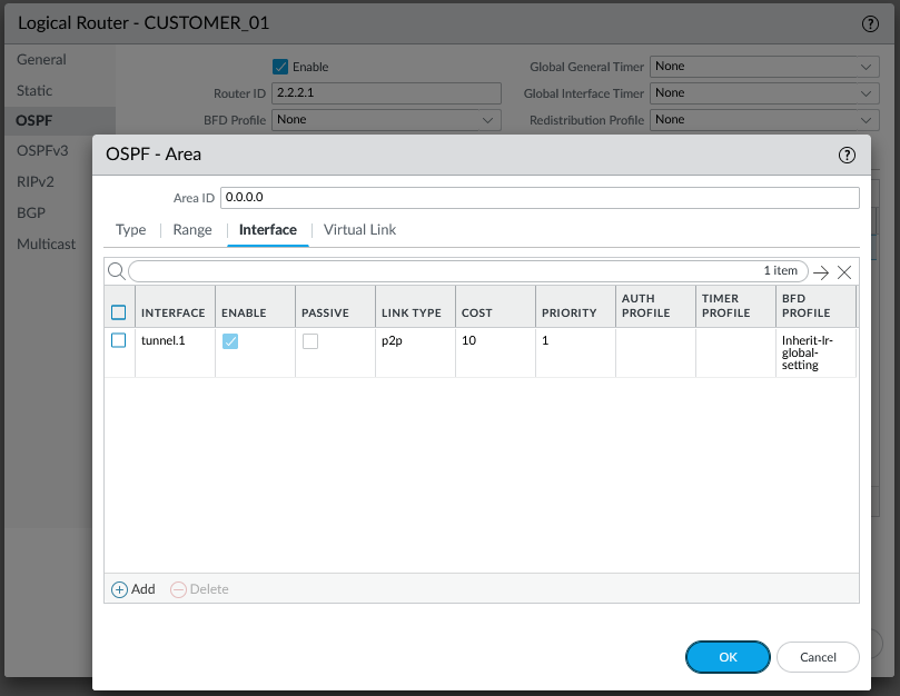
To bring up the IPSec tunnel, you need to send traffic via the tunnel.1 interface, so lets configure OSPF. Although the IKE gateway is using the loopback interface in the WAN VR, the tunnel.1 interface is a member of the CUSTOMER_01 VR, so we need to configure the OSPF process there. Nothing sophisticated, just confiugre both firewalls to be in Area 0, using the tunnel.1 interface as a p2p link since it is a /30 subnet with only two speakers:
By default inter-zone flows are denied, to lock down the firewall I recommend overriding the built-in intra-zone rule and setting it to deny. An explict rule for the IPSec tunnel in then required for the intra-zone flow:

set rulebase security rules IPSec to WAN
set rulebase security rules IPSec from WAN
set rulebase security rules IPSec source [ 2.2.2.1/32 2.2.2.2/32 ]
set rulebase security rules IPSec destination [ 2.2.2.1/32 2.2.2.2/32 ]
set rulebase security rules IPSec source-user any
set rulebase security rules IPSec category any
set rulebase security rules IPSec application [ ike ipsec ]
set rulebase security rules IPSec service application-default
set rulebase security rules IPSec source-hip any
set rulebase security rules IPSec destination-hip any
set rulebase security rules IPSec action allow
Commit
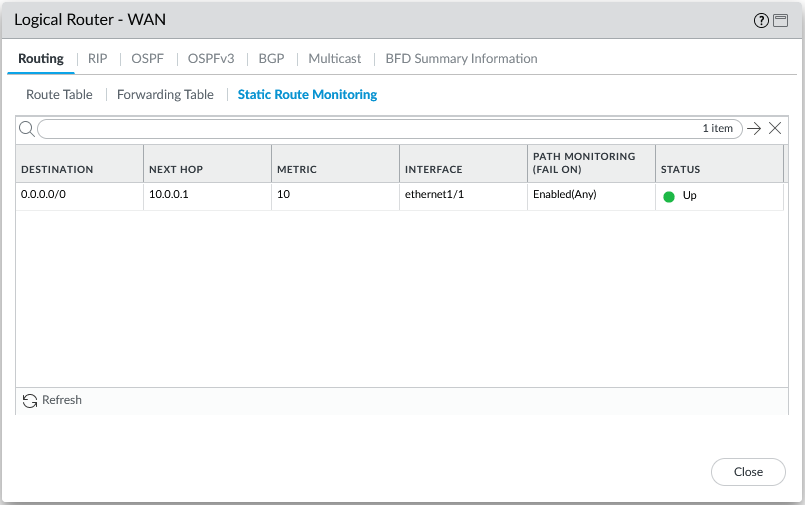
Hit the commit button and then start checking the runtime information. First check the static route monitoring and check at the very least you can reach the WAN next-hop router. If this is not working, then none of the other configuration will function:
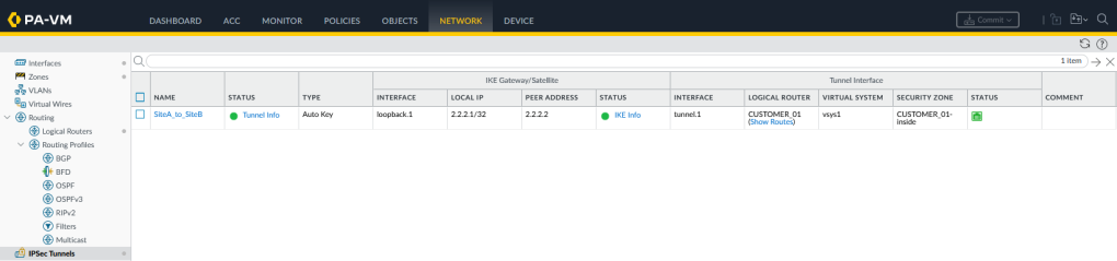
Confirm the IKE and IPSec tunnel status is UP:
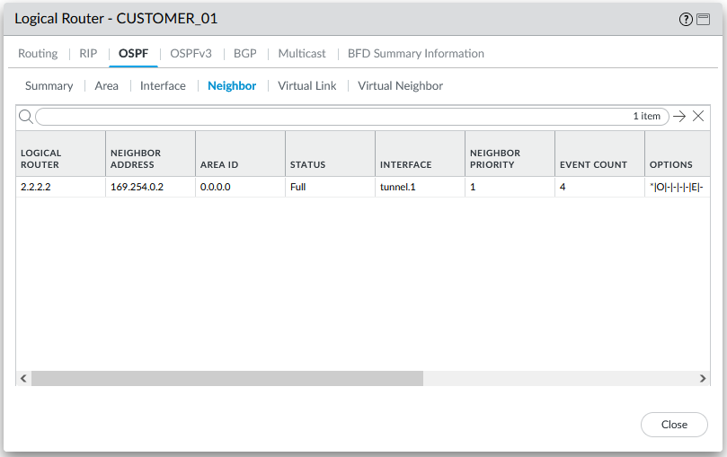
With the IPSec tunnel running across the WAN, the tunnel.1 interface should be functional between both firewall CUSTOMER_01 VRs, the OSPF process should therefore see one OSPF neighbour on the tunnel.1 interface:
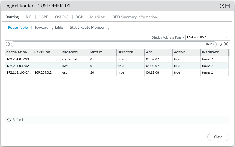
Checking the routing table on CUSTOMER_01 we can see one prefix being recieved from SiteB, also more crucial to our topology we have connectivity across the WAN but no WAN prefixes:
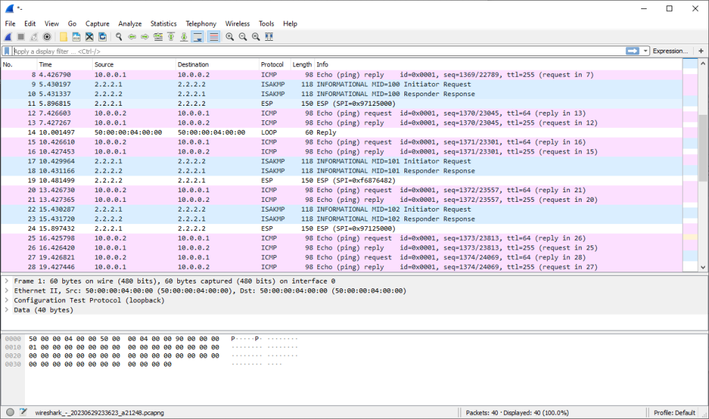
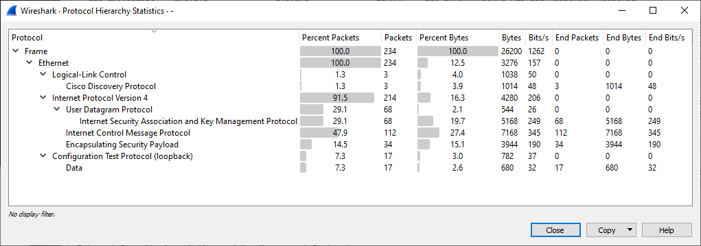
As a final check we can confirm via a packet capture on the Ethernet1/1 WAN interface we can see that only encrypted packets from the IPSec tunnel and ICMP packets from the static route monitor:

Leave a comment